Cross-section Main Input Template (uh60a_section.xml.tmp)#
This file contains the overall design of the cross-section.
All data are enclosed in a root tag <cross_section>.
It contains the following sections: include, analysis, general, geometry, layups and components.
1<cross_section name="uh60a_section" format="1">
2    ...
3</cross_section>
The format 0 refers to the old format where base lines and layups definition are given in separate files. The format 1 is the new format where these information are included in the main cross section definition file.
Note
A natural procedure of preparing this file would be:
1. Create the xml file with arbitrary values for parameters and run PreVABS to check syntax errors.
2. If no error, for those quantities that will receive values from Dakota, replace the value with the parameter name enclosed by {}.
Note
For more detailed instruction, please go to the PreVABS documentation
Section 1: Including files#
1<include>
2    <material>material_database</material>
3</include>
The material database is included here. The .xml extension is omitted.
Section 2: Analysis settings#
1<analysis>
2    <model>1</model>
3</analysis>
model being 0 means classical analysis only. model being 1 means both classical and refined/Timoshenko analysis.
Section 3: General settings#
1<general>
2    <translate>{oa2} 0</translate>
3    <scale>{chord}</scale>
4    <mesh_size>{mesh_size}</mesh_size>
5    <element_type>linear</element_type>
6</general>
This part defines translation, scaling, rotating, global mesh size and element types.
The transformation is done in the order of translation, scaling and rotating.
The placeholder {} is put here for dakota to fill in with a number.
Section 4: Geoemtry#
Primitives#
We will first introduce the format for defining geometry
Base point#
Base points can be added by including a data file or created directly in the input file.
Include base points#
1<basepoints>
2    <include>sc1095</include>
3</basepoints>
This refers to sc1095.dat base points definition file. The extension is omitted here. This file is introduced in Section Cross-section Airfoil Data (sc1095.dat).
Individual base points#
By coordinates:
1<point name="pnsmc">{pnsmc_a2} {pnsmc_a3}</point>
A new point is defined by x2 and x3 coordinates.
By intersections:
1<point name="p5" on="bsl_upper" by="x2">-0.02</point>
The points is the intersection of the “bsl_upper” and “x2=-0.02”. This is done before any scaling, translating or rotating.
Base line#
Define a straight base line by a sequence of points.
1<baseline name="bsl_le" type="straight">
2    <points>p6:141,1:p5</points>
3</baseline>
1 and 141 are points in the data file.
p5 and p6 are points defined by intersection.
The intersecton point can be inserted back into the data file.
When you use pA:pB, all points between the two are included in the base line.
Define a circular base line.
1<baseline name="bsl_nsm" type="circle">
2    <center>pnsmc</center>
3    <radius>{nsmr}</radius>
4    <discrete by="angle">9</discrete>
5</baseline>
This is a circular base line defined for the non-structural mass using a center and a radius. The discrete tag specifies number of lines this circle is divided into.
Build the geometry#
First, we need to define some additional base points
1<point name="p1" on="bsl_upper" by="x2">{wl_a2}</point>
2<point name="p2" on="bsl_upper" by="x2">{wt_a2}</point>
3<point name="p3" on="bsl_lower" by="x2">{wt_a2}</point>
4<point name="p4" on="bsl_lower" by="x2">{wl_a2}</point>
5<point name="p5" on="bsl_upper" by="x2">-0.02</point>
6<point name="p6" on="bsl_lower" by="x2">-0.02</point>
7<point name="p7" on="bsl_upper" by="x2">-0.8</point>
8<point name="p8" on="bsl_lower" by="x2">-0.8</point>
9<point name="pnsmc">{pnsmc_a2} {pnsmc_a3}</point>
Now we have all the pieces. We can primitives and base points introduced to define some base lines. The base lines and base points are illustrated in Fig. 6. The point 1 is the rightmost point or starting point; the point 71 is leftmost point on the upper half; the point 72 is the leftmost point on the lower half (71 and 72 has the same x2 value); the point 141 is the last point before getting back to the starting point.
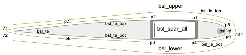
Figure 6 Base lines and base points definition#
The upper half of the airfoil
1<baseline name="bsl_upper" type="straight">
2    <points>1:71</points>
3</baseline>
The lower half of the airfoil
1<baseline name="bsl_lower" type="straight">
2    <points>72:141,1</points>
3</baseline>
The spar box
1<baseline name="bsl_spar_all" type="straight">
2    <points>p1:p2,p3:p4,p1</points>
3</baseline>
p1, p2, p3, p4 are defined by intersections of web locations and airfoil.
The leading edge
1<baseline name="bsl_le_top" type="straight">
2    <points>p5:p1</points>
3</baseline>
4<baseline name="bsl_le" type="straight">
5    <points>p6:141,1:p5</points>
6</baseline>
7<baseline name="bsl_le_bot" type="straight">
8    <points>p4:p6</points>
9</baseline>
The trailing edge
1<baseline name="bsl_te_top" type="straight">
2    <points>p2:p7</points>
3</baseline>
4<baseline name="bsl_te" type="straight">
5    <points>p7:71,72:p8</points>
6</baseline>
7<baseline name="bsl_te_bot" type="straight">
8    <points>p8:p3</points>
9</baseline>
Section 5: Layups#
1<layup name="lyp_spar">
2    <layer lamina="{mn_spar_1}">{fo_spar_1}:{np_spar_1}</layer>
3    <layer lamina="{mn_spar_1}">{fo_spar_2}:{np_spar_2}</layer>
4    <layer lamina="{mn_spar_1}">{fo_spar_3}:{np_spar_3}</layer>
5    <layer lamina="{mn_spar_1}">{fo_spar_4}:{np_spar_4}</layer>
6</layup>
Each layup tag could include multiple layer tags. For each layer tag, you need to specify lamina as defined in material database, fiber orientation and number of plies. For definition of other layups, refer to the complete input file Listing 1.
Section 6: Components#
There are 6 components in the cross section model: the spar box, the leading edge, the trailing edge, the non-structural mass, the filling on the leading and trailing edge.
Component format#
 1<component name="[string]">
 2    <segment>
 3        <baseline> [string] </baseline>
 4        <layup> [string] </layup>
 5    </segment>
 6    </segments>
 7        <baseline> [string] </baseline>
 8        <layup (begin="[number]") (end="[number]")> [string] </layup>
 9        <layup> [string] </layup>
10    </segments>
11</component>
You can include arbitrary number of segment/segments.
The segment tag is for simple definitions.
The segments tag allows you to specify multiple layups to be stacked.
It also allows you to specify the parametric starting and end location of the layup on the base line.
The spar box
1<component name="spar">
2<segments>
3    <baseline>bsl_spar_all</baseline>
4    <layup>lyp_skin_graphite</layup>
5    <layup>lyp_spar</layup>
6</segments>
7</component>
We use the aforementioned
bsl_spar_allbase line. Two layups are stacked on the base line.The leading edge
 1<component name="le" depend="spar">
 2    <segments>
 3        <baseline>bsl_le</baseline>
 4        <layup>lyp_steel</layup>
 5        <layup>lyp_skin_graphite</layup>
 6        <layup>lyp_le</layup>
 7    </segments>
 8    <segments>
 9        <baseline>bsl_le_top</baseline>
10        <layup>lyp_steel</layup>
11        <layup>lyp_skin_graphite</layup>
12        <layup>lyp_le</layup>
13    </segments>
14    <segments>
15        <baseline>bsl_le_bottom</baseline>
16        <layup>lyp_steel</layup>
17        <layup>lyp_skin_graphite</layup>
18        <layup>lyp_le</layup>
19    </segments>
20</component>
This component includes 3 segments. They use the 3 base lines defined for leading edge. The leading edge component has connection with the spar component. This is indicated in the depend attribute.
The trailing edge
 1<component name="te" depend="spar">
 2    <segments>
 3        <baseline>bsl_te_top</baseline>
 4        <layup>lyp_skin_graphite</layup>
 5        <layup>lyp_te</layup>
 6    </segments>
 7    <segment>
 8        <baseline>bsl_te</baseline>
 9        <layup>lyp_skin_graphite</layup>
10    </segment>
11    <segments>
12        <baseline>bsl_te_bottom</baseline>
13        <layup>lyp_skin_graphite</layup>
14        <layup>lyp_te</layup>
15    </segments>
16</component>
This component also includes 3 segments. The trailing edge component has connection with the spar component. This is indicated in the depend attribute.
The non-structural mass
1<component name="nsm" type="fill" depend="le">
2    <baseline>bsl_nsm</baseline>
3    <location>pnsmc</location>
4    <material>lead</material>
5    <theta3>0</theta3>
6    <mesh_size at="pnsmc">{mesh_size_fill}</mesh_size>
7</component>
The non-structural mass is a circular area filled with a material. So we specify the type to be
fill. The circular baseline bsl_nsmis used as the boundary. The base pointpnsmcis used to tell the program which side of the base line is to be filled. Themesh_sizeis to set local mesh size at the given position.The filling
 1<component name="fill_le" type="fill" depend="spar,le,nsm">
 2    <location>pfle1</location>
 3    <material>Rohacell 70</material>
 4    <theta3>0</theta3>
 5    <mesh_size at="pfle1,pfle2">{mesh_size_fill}</mesh_size>
 6</component>
 7<component name="fill_te" type="fill" depend="spar,te">
 8    <location>pfte1</location>
 9    <material>Plascore PN2-3/16OX3.0</material>
10    <theta3>0</theta3>
11    <mesh_size at="pfte1,pfte2">{mesh_size_fill}</mesh_size>
12</component>
The component is similar to the non-structural mass definition. Notice that they depend on the components that they have connection with. The
locationis to tell the where to fill the material. Local mesh size control is used to refine the mesh near the specified location.
Complete file#
  1<cross_section name="uh60a_section" format="1">
  2    <include>
  3        <material>material_database</material>
  4    </include>
  5    <analysis>
  6        <model>1</model>
  7    </analysis>
  8    <general>
  9        <translate>{oa2} 0</translate>
 10        <scale>{chord}</scale>
 11        <mesh_size>{mesh_size}</mesh_size>
 12        <element_type>linear</element_type>
 13    </general>
 14    <baselines>
 15        <basepoints>
 16            <include>sc1095</include>
 17        </basepoints>
 18        <baseline name="bsl_upper" type="straight">
 19            <points>1:71</points>
 20        </baseline>
 21        <baseline name="bsl_lower" type="straight">
 22            <points>72:141,1</points>
 23        </baseline>
 24        <point name="p1" on="bsl_upper" by="x2">{wl_a2}</point>
 25        <point name="p2" on="bsl_upper" by="x2">{wt_a2}</point>
 26        <point name="p3" on="bsl_lower" by="x2">{wt_a2}</point>
 27        <point name="p4" on="bsl_lower" by="x2">{wl_a2}</point>
 28        <point name="p5" on="bsl_upper" by="x2">-0.02</point>
 29        <point name="p6" on="bsl_lower" by="x2">-0.02</point>
 30        <point name="p7" on="bsl_upper" by="x2">-0.8</point>
 31        <point name="p8" on="bsl_lower" by="x2">-0.8</point>
 32        <baseline name="bsl_spar_all" type="straight">
 33            <points>p1:p2,p3:p4,p1</points>
 34        </baseline>
 35        <baseline name="bsl_le_top" type="straight">
 36            <points>p5:p1</points>
 37        </baseline>
 38        <baseline name="bsl_le" type="straight">
 39            <points>p6:141,1:p5</points>
 40        </baseline>
 41        <baseline name="bsl_le_bottom" type="straight">
 42            <points>p4:p6</points>
 43        </baseline>
 44        <baseline name="bsl_te_top" type="straight">
 45            <points>p2:p7</points>
 46        </baseline>
 47        <baseline name="bsl_te" type="straight">
 48            <points>p7:71,72:p8</points>
 49        </baseline>
 50        <baseline name="bsl_te_bottom" type="straight">
 51            <points>p8:p3</points>
 52        </baseline>
 53        <point name="pnsmc">{pnsmc_a2} {pnsmc_a3}</point>
 54        <baseline name="bsl_nsm" type="circle">
 55            <center>pnsmc</center>
 56            <radius>{nsmr}</radius>
 57            <discrete by="angle">9</discrete>
 58        </baseline>
 59        <!--
 60            The following four points are used to define locations of larger
 61            mesh size in the two filling regions.
 62        -->
 63        <point name="pfle1">{pnsmc_a2 - nsmr - 0.005} 0</point>
 64        <point name="pfle2">{wl_a2 + 0.005} 0</point>
 65        <point name="pfte1">{wt_a2 - 0.01} 0</point>
 66        <point name="pfte2">{pfte2_a2} 0</point>
 67    </baselines>
 68
 69    <layups>
 70        <layup name="lyp_steel">
 71            <layer lamina="Aluminum 8009_0.01">0:2</layer>
 72        </layup>
 73        <layup name="lyp_skin_graphite">
 74            <layer lamina="T300 15k/976_0.0053">0:2</layer>
 75        </layup>
 76        <layup name="lyp_spar">
 77            <layer lamina="{mn_spar_1}">{fo_spar_1}:{np_spar_1}</layer>
 78            <layer lamina="{mn_spar_1}">{fo_spar_2}:{np_spar_2}</layer>
 79            <layer lamina="{mn_spar_1}">{fo_spar_3}:{np_spar_3}</layer>
 80            <layer lamina="{mn_spar_1}">{fo_spar_4}:{np_spar_4}</layer>
 81        </layup>
 82        <layup name="lyp_le">
 83            <layer lamina="{mn_le}">{fo_le}:{np_le}</layer>
 84        </layup>
 85        <layup name="lyp_te">
 86            <layer lamina="{mn_te}">{fo_te}:{np_te}</layer>
 87        </layup>
 88    </layups>
 89
 90    <component name="spar">
 91        <segments>
 92            <baseline>bsl_spar_all</baseline>
 93            <layup>lyp_skin_graphite</layup>
 94            <layup>lyp_spar</layup>
 95        </segments>
 96    </component>
 97    <component name="le" depend="spar">
 98        <segments>
 99            <baseline>bsl_le</baseline>
100            <layup>lyp_steel</layup>
101            <layup>lyp_skin_graphite</layup>
102            <layup>lyp_le</layup>
103        </segments>
104        <segments>
105            <baseline>bsl_le_top</baseline>
106            <layup>lyp_steel</layup>
107            <layup>lyp_skin_graphite</layup>
108            <layup>lyp_le</layup>
109        </segments>
110        <segments>
111            <baseline>bsl_le_bottom</baseline>
112            <layup>lyp_steel</layup>
113            <layup>lyp_skin_graphite</layup>
114            <layup>lyp_le</layup>
115        </segments>
116    </component>
117    <component name="te" depend="spar">
118        <segments>
119            <baseline>bsl_te_top</baseline>
120            <layup>lyp_skin_graphite</layup>
121            <layup>lyp_te</layup>
122        </segments>
123        <segment>
124            <baseline>bsl_te</baseline>
125            <layup>lyp_skin_graphite</layup>
126        </segment>
127        <segments>
128            <baseline>bsl_te_bottom</baseline>
129            <layup>lyp_skin_graphite</layup>
130            <layup>lyp_te</layup>
131        </segments>
132    </component>
133    <component name="nsm" type="fill" depend="le">
134        <baseline>bsl_nsm</baseline>
135        <location>pnsmc</location>
136        <material>lead</material>
137        <theta3>0</theta3>
138        <mesh_size at="pnsmc">{mesh_size_fill}</mesh_size>
139    </component>
140    <component name="fill_le" type="fill" depend="spar,le,nsm">
141        <location>pfle1</location>
142        <material>Rohacell 70</material>
143        <theta3>0</theta3>
144        <mesh_size at="pfle1,pfle2">{mesh_size_fill}</mesh_size>
145    </component>
146    <component name="fill_te" type="fill" depend="spar,te">
147        <location>pfte1</location>
148        <material>Plascore PN2-3/16OX3.0</material>
149        <theta3>0</theta3>
150        <mesh_size at="pfte1,pfte2">{mesh_size_fill}</mesh_size>
151    </component>
152</cross_section>