Cross-sectional Parameterization and Beam Properties#
The cross-section is comprised of the following components: box spar, front laminate, back laminate, front filling, back filling and non-structural mass, as shown in Fig. 3.
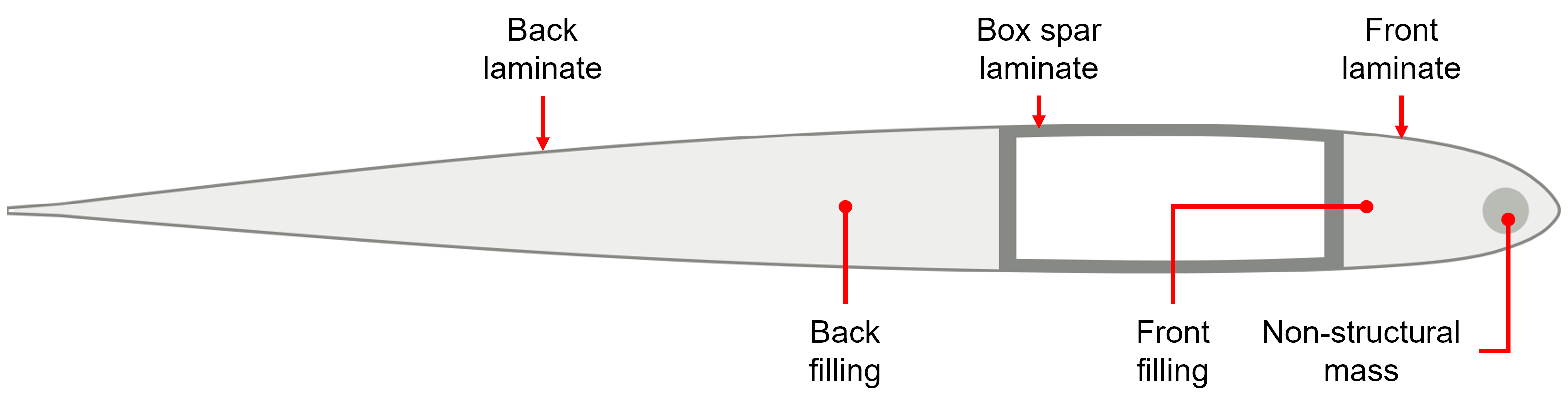
Figure 3 Components of the cross-section.#
Parameterization#
Parameters can be in general grouped into two sets, geometry related and layup related.
Geometry#
In this example, four geometric parameters are defined in the non-dimensional frame where the chord length is 1, as shown in Fig. 4. The origin of this frame is placed at the leading edge. The size and location of the box spar are defined by the two parameters \(a_2^{wl}\) and \(a_2^{wt}\), which are in fact the horizontal coordinates of the leading and trailing webs, respectively. The non-structural mass is assumed to be a circular object in this example. Hence, the three parameters defining the size and location are the horizontal coordinate \(a_2^{nsm}\) and vertical coordinate \(a_3^{nsm}\) of the center, and the radius \(r^{nsm}\).
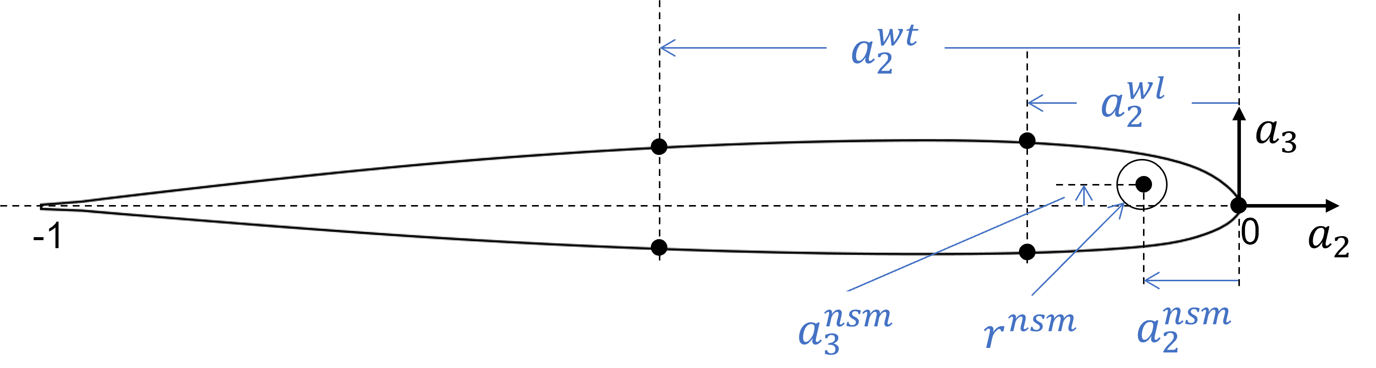
Figure 4 Parameters for the geometry in the non-dimensional frame, where the chord length is 1.#
Layup#
Layup related parameters are used to define materials (\(l\)), fiber angles (\(\theta\)) and numbers of plies (\(n\)) for the laminates of box spar, cap and overwrap. In this example, the box spar laminate is assumed to have four layers. All four layers have the same material (\(l^s\)), but can have different fiber angles (\(\theta_1^s, \theta_2^s, \theta_3^s, \theta_4^s\)) and numbers of plies (\(n_1^s, n_2^s, n_3^s, n_4^s\)). The cap laminate is assumed to have a single layer with three parameters: \(l^c, \theta^c, n^c\). The overwrap laminate is also assumed having a single layer with three parameters: \(l^o, \theta^o, n^o\).
The overall layup design of the three lamiante components are listed in Table 4, Table 5 and Table 6.
Layer |
Lamina |
Fiber angle [deg] |
Ply count |
|---|---|---|---|
Base |
T300 15k/976 |
0 |
2 |
1 |
\(l^s\) |
\(\theta^s_1\) |
\(n^s_1\) |
2 |
\(l^s\) |
\(\theta^s_2\) |
\(n^s_2\) |
3 |
\(l^s\) |
\(\theta^s_3\) |
\(n^s_3\) |
4 |
\(l^s\) |
\(\theta^s_4\) |
\(n^s_4\) |
Layer |
Lamina |
Fiber angle [deg] |
Ply count |
|---|---|---|---|
Cap |
Aluminum 8009 |
0 |
2 |
Base |
T300 15k/976 |
0 |
2 |
1 |
\(l^f\) |
\(\theta^f\) |
\(n^f\) |
Layer |
Lamina |
Fiber angle [deg] |
Ply count |
|---|---|---|---|
Base |
T300 15k/976 |
0 |
2 |
1 |
\(l^b\) |
\(\theta^b\) |
\(n^b\) |
A summary of the parameters is listed in Table 7.
Symbol |
Name in input files |
Description |
|---|---|---|
\(a_2^{wl}\) |
|
Non-dimensional horizontal coordinate of the leading web of the box spar |
\(a_2^{wt}\) |
|
Non-dimensional horizontal coordinate of the trailing web of the box spar |
\(a_2^{nsm}\) |
|
Non-dimensional horizontal coordinate of the center of the non-structural mass |
\(a_3^{nsm}\) |
|
Non-dimensional vertical coordinate of the center of the non-structural mass |
\(r^{nsm}\) |
|
Non-dimensional radius of the non-structural mass |
\(l^s\) |
|
Material (lamina) selection of the box spar layup |
\(\theta_1^s\) |
|
Fiber angle of layer 1 of the box spar layup |
\(\theta_2^s\) |
|
Fiber angle of layer 2 of the box spar layup |
\(\theta_3^s\) |
|
Fiber angle of layer 3 of the box spar layup |
\(\theta_4^s\) |
|
Fiber angle of layer 4 of the box spar layup |
\(n_1^s\) |
|
Number of plies of layer 1 of the box spar layup |
\(n_2^s\) |
|
Number of plies of layer 2 of the box spar layup |
\(n_3^s\) |
|
Number of plies of layer 3 of the box spar layup |
\(n_4^s\) |
|
Number of plies of layer 4 of the box spar layup |
\(l^c\) |
|
Material (lamina) selection of the cap layup |
\(\theta^c\) |
|
Fiber angle of the cap layup |
\(n^c\) |
|
Number of plies of the cap layup |
\(l^o\) |
|
Material (lamina) selection of the overwrap layup |
\(\theta^o\) |
|
Fiber angle of the overwrap layup |
\(n^o\) |
|
Number of plies of the overwrap layup |
Some other parameters used are listed below:
Name in input files |
Description |
|---|---|
|
Chord length of the cross-section |
|
Non-dimensional horizontal coordinate of the origin of the frame \(\mathbf{x}\) used in VABS. |
|
Non-dimensional location of point marking the coarse meshes in the filling region |
|
Global mesh size |
|
Mesh size for the filling regions |
Materials#
Materials used in this example are summarized in Table 9. Lamina thickness is given in Table 10. ‘Aluminum 80009’ is used as the outermost layer of the cap. ‘Lead’ is used for the non-structural mass. ‘Rohacell 70’ is used at the leading filling region. ‘Plascore PN2-3/16OX3.0’ is used at the trailing filling region. ‘T300 15k/976’ is used as the base layer for the spar, cap and overwrap, to prevent zero layers during the optimization. The last four rows in the table are the candidate materials for the layup design of the three components.
Material |
Density |
\(E_1\) |
\(E_2\) |
\(E_3\) |
\(\nu_{12}\) |
\(\nu_{13}\) |
\(\nu_{23}\) |
\(G_{12}\) |
\(G_{13}\) |
\(G_{23}\) |
|---|---|---|---|---|---|---|---|---|---|---|
[\(\mathrm{lbf\cdot s^2/in^4}\)] |
[\(\mathrm{psi}\)] |
[\(\mathrm{psi}\)] |
[\(\mathrm{psi}\)] |
[\(\mathrm{psi}\)] |
[\(\mathrm{psi}\)] |
[\(\mathrm{psi}\)] |
||||
Aluminum 8009 |
\(0.271959\times 10^{-3}\) |
\(13.1\times 10^6\) |
\(0.33\) |
|||||||
Lead |
\(1.060957\times 10^{-3}\) |
\(1.0\times 10^{-3}\) |
\(0\) |
|||||||
Rohacell 70 |
\(7.040895\times 10^{-6}\) |
\(13.125\times 10^3\) |
\(13.125\times 10^3\) |
\(13.125\times 10^3\) |
\(0.315\) |
\(0.315\) |
\(0.300\) |
\(4.118\times 10^3\) |
\(4.118\times 10^3\) |
\(4.118\times 10^3\) |
Plascore PN2-3/16OX3.0 |
\(4.509066\times 10^{-6}\) |
\(1.0\times 10^3\) |
\(1.0\times 10^3\) |
\(20\times 10^3\) |
\(0.30\) |
\(0.01\) |
\(0.01\) |
\(1.0\times 10^3\) |
\(3.5\times 10^3\) |
\(5.799\times 10^3\) |
T300 15k/976 |
\(0.149716\times 10^{-3}\) |
\(19.6\times 10^6\) |
\(1.34\times 10^6\) |
\(0.348\) |
\(0.91\times 10^6\) |
|||||
AS4 12k/E7K8 |
\(0.145973\times 10^{-3}\) |
\(19.3\times 10^6\) |
\(1.23\times 10^6\) |
\(0.32\) |
\(7.31\times 10^6\) |
|||||
S2/SP381 |
\(0.173109\times 10^{-3}\) |
\(7.05\times 10^6\) |
\(1.97\times 10^6\) |
\(0.263\) |
\(0.59\times 10^6\) |
|||||
T650-35 12k/976 |
\(0.148781\times 10^{-3}\) |
\(22.0\times 10^6\) |
\(1.30\times 10^6\) |
\(0.115\) |
\(0.745\times 10^6\) |
|||||
T700 24K/E765 |
\(0.145037\times 10^{-3}\) |
\(18.71\times 10^6\) |
\(1.36\times 10^6\) |
\(0.319\) |
\(0.65\times 10^6\) |
Material |
Thickness [\(in\)] |
|---|---|
Aluminum 8009 |
0.01 |
T300 15k/976 |
0.0053 |
AS4 12k/E7K8 |
0.0054 |
S2/SP381 |
0.0092 |
T650-35 12k/976 |
0.0052 |
T700 24K/E765 |
0.0056 |
Properties#
The beam properties calculated by VABS listed in Table 11 will be needed in the optimization. Fig. 5 shows the points and axes with respect to which some properties are calculated. The two bending stiffnesses are given with respect to the principal bending axes. The horizontal locations of the shear and mass centers are given with respect to the modeling origin, which is the quarder chord in this example.
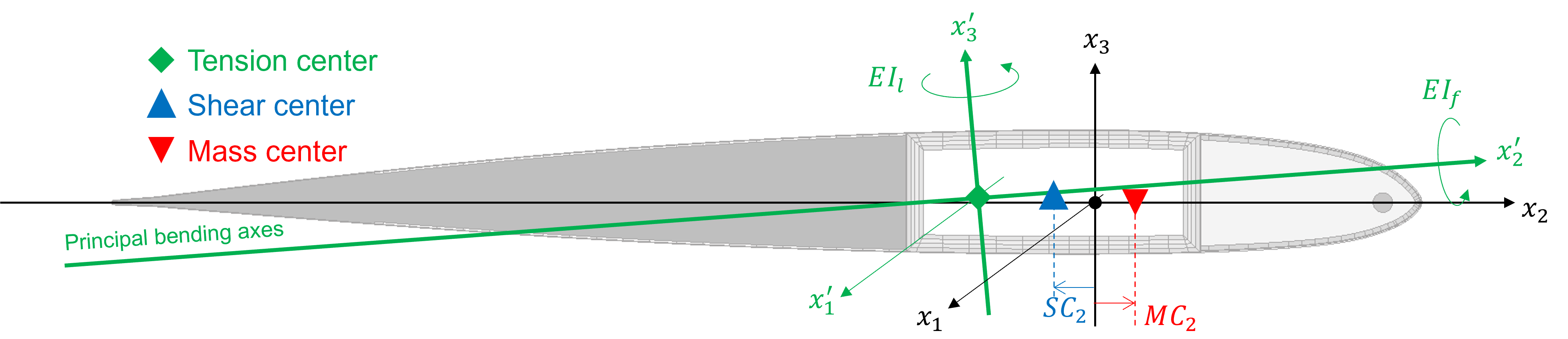
Figure 5 Beam properties and their reference of calculation.#
A summary of the properties is listed in Table 11.
Symbol |
Name in input files |
Description |
|---|---|---|
\(m\) |
|
Mass per unit length |
\(GJ\) |
|
Torsional stiffness |
\(EI_f\) |
|
Flapping bending stiffness |
\(EI_l\) |
|
Lead-lag bending stiffness |
\(SC_2\) |
|
Horizontal coordinate of the shear center in the frame x. |
\(MC_2\) |
|
Horizontal coordinate of the mass center in the frame x. |