Coordinate systems#
There are three coordinate frames used in PreVABS as shown in Fig. 31:
z is a basic frame, for the normalized airfoil data points for instance;
x is the final frame;
y is the local frame for each element.
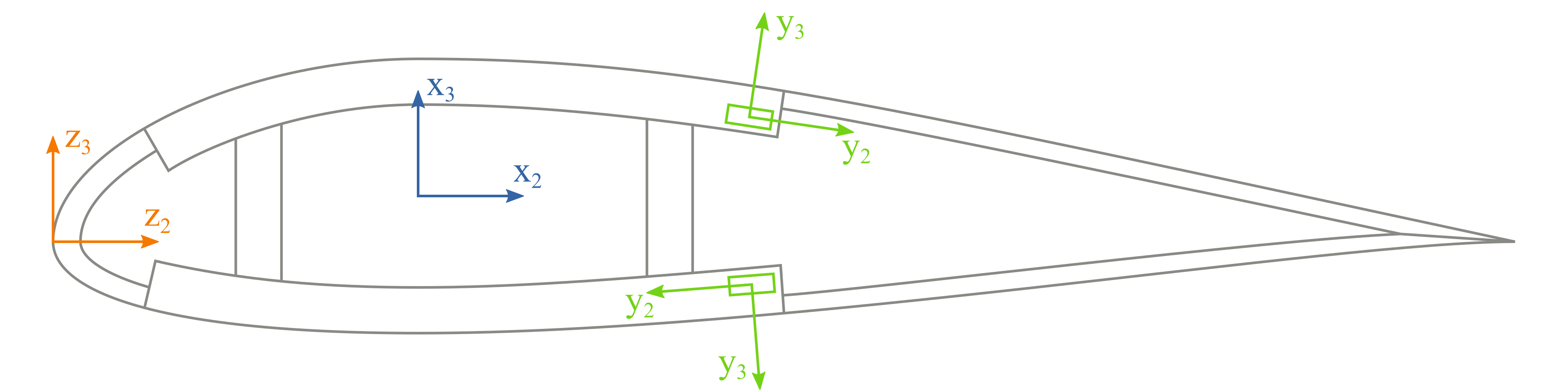
Figure 31 The basic, cross-sectional and elementary frames in a cross section.#
Here, \(z_1\), \(x_1\) and \(y_1\) are parallel to the tangent of the beam reference line and pointing out of the paper. The basic frame is where base points are defined. The cross-sectional and elementary frames have the same definitions as those in VABS. User can define the topology of a cross section in the basic frame z and use manipulations like translation, scaling and rotation to generate the actual geometry in x. For an airfoil cross section, airfoil surface data points downloaded from a database having chord length 1 are in the frame z, and they are transformed into the frame x through translation (re-define the origin), scaling (multiplied by the actual chord length), and rotation (attack angle) if necessary, as shown in Fig. 32. More details about this transformation can be found in Section: Other input settings below.
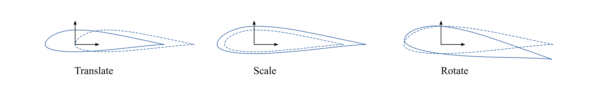
Figure 32 Three manipulations to transform a cross section.#
In PreVABS, the definition of the elementary frame y follows the rule that the positive direction of \(y_2\) axis is always the same as the direction of the base line, and then \(y_3\) is generated based on \(y_1\) and \(y_2\) according to the right-hand rule. More details about the base line can be found in Geometry and shapes.