Materials and layups#
PreVABS uses the keyword material for the physical properties attached to any materials, while lamina for material plus thickness, which in a sense is fixed by manufacturers.
This can be thought as the basic commercially available “material”, such as a composite preprag.
A layer is a stack of laminae with the same fiber orientation.
The thickness of a layer can only be a multiplier of the lamina thickness.
Layup is several layers stacked together in a specific order.
This relationship is illustrated in Fig. 38.
More details can be found below.
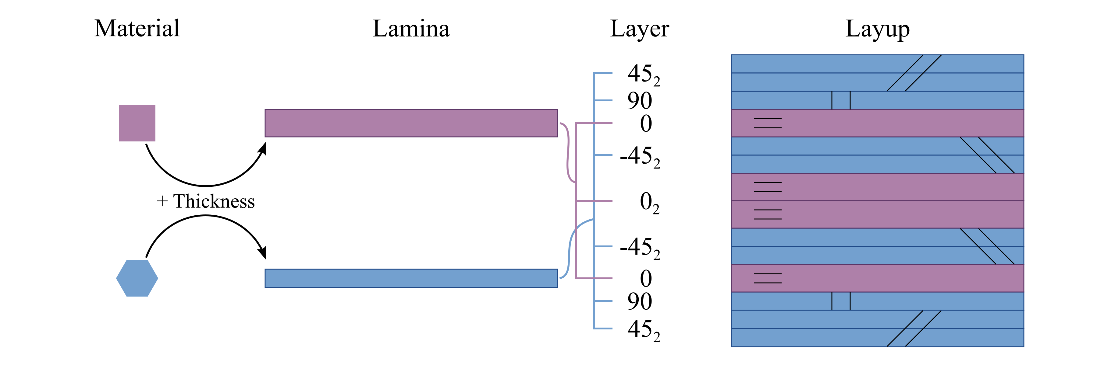
Figure 38 Relationship between material, lamina, layer and layup.#
Material#
Both materials and laminae are stored in one XML file, under the single root element <materials>.
A template of this file is shown in Listing 43.
Each material must have a name and type. Under each <material> element, there are a <density> element and an <elastic> element.
If failure analysis is wanted, users need to provide extra data including <strength> and <failure_criterion>.
 1<materials>
 2  ...
 3  <material name="..." type="...">
 4    <density>...</density>
 5    <elastic>...</elastic>
 6    <strength>...</strength>
 7    <failure_criterion>...</failure_criterion>
 8  </material>
 9  ...
10</materials>
Specification
<material> - Root element for each material.
name - Name of the material.
type - Type of the material. Choose one from ‘isotropic’, ‘orthotropic’, ‘anisotropic’ and ‘lamina’.
<density> - Density of the material. Defualt is 1.0.
<elastic> - Elastic properties of the material. Specifications are different for different types.
<strength> - Strength properties of the material. Specifications are different for different types and different failure criterion.
<failure_criterion> - Failure criterion of the material. Options are different for different types.
Elastic properties#
 1<materials>
 2  ...
 3  <material name="iso1" type="isotropic">
 4    <elastic>
 5      <e>...</e>
 6      <nu>...</nu>
 7    </elastic>
 8  </material>
 9
10  <material name="lam1" type="lamina">
11    <elastic>
12      <e1>...</e1>
13      <e2>...</e2>
14      <nu12>...</nu12>
15      <g12>...</g12>
16    </elastic>
17  </material>
18
19  <material name="orth1" type="orthotropic">
20    <elastic>
21      <e1>...</e1>
22      <e2>...</e2>
23      <e3>...</e3>
24      <g12>...</g12>
25      <g13>...</g13>
26      <g23>...</g23>
27      <nu12>...</nu12>
28      <nu13>...</nu13>
29      <nu23>...</nu23>
30    </elastic>
31  </material>
32
33  <material name="aniso1" type="anisotropic">
34    <elastic>
35      <c11>...</c11>
36      <c12>...</c12>
37      <c13>...</c13>
38      <c14>...</c14>
39      <c15>...</c15>
40      <c16>...</c16>
41      <c22>...</c22>
42      <c23>...</c23>
43      <c24>...</c24>
44      <c25>...</c25>
45      <c26>...</c26>
46      <c33>...</c33>
47      <c34>...</c34>
48      <c35>...</c35>
49      <c36>...</c36>
50      <c44>...</c44>
51      <c45>...</c45>
52      <c46>...</c46>
53      <c55>...</c55>
54      <c56>...</c56>
55      <c66>...</c66>
56    </elastic>
57  </material>
58  ...
59</materials>
For the lamina type material, the code will internally convert it to the orthotropic type, by assigning the rest five constants in the following way:
e3 = e2
nu13 = nu12
nu23 = 0.3
g13 = g12
g23 = e2 / ( 2 * (1 + nu23) )
Specification
If type=”isotropic” - 2 constants: ‘e’ and ‘nu’.
If type=”lamina” - 4 constants: ‘e1’, ‘e2’, ‘nu12’ and ‘g12’.
If type=”orthotropic” - 9 constants: ‘e1’, ‘e2’, ‘e3’, ‘g12’, ‘g13’, ‘g23’, ‘nu12’, ‘nu13’ and ‘nu23’.
If type=”anisotropic” - 21 constants: ‘c11’, ‘c12’, ‘c13’, ‘c14’, ‘c15’, ‘c16’, ‘c22’, ‘c23’, ‘c24’, ‘c25’, ‘c26’, ‘c33’, ‘c34’, ‘c35’, ‘c36’, ‘c44’, ‘c45’, ‘c46’, ‘c55’, ‘c56’ and ‘c66’. These constants are defined in Equation (2).
If type=”lamina” - 4 constants: ‘e1’, ‘e2’, ‘g12’ and ‘nu12’. Internally, this type of material will be converted to the ‘orthotropic’ material. The default values for the rest components are: ‘e3=e2’, ‘nu13=nu12’, ‘nu23=0.3’, ‘g13=g12’ and ‘g23=e3/(2*(1+nu23))’. These default values can be overwritten by custom values.
Strength properties#
Inputs for strength properties for all types of materials have the same syntax. For each material, users can input at least one or at most nine properties. The overall syntax for each material is shown in Listing 44.
 1<material name="..." type="...">
 2  <failure_criterion>...</failure_criterion>
 3  <strength>
 4    <xt>...</xt>
 5    <yt>...</yt>
 6    <zt>...</zt>
 7    <xc>...</xc>
 8    <yc>...</yc>
 9    <zc>...</zc>
10    <r>...</r>
11    <t>...</t>
12    <s>...</s>
13  </strength>
14</material>
Although all properties will be stored internally, only some of them will be used in analysis depending on the failure criterion.
Specification
<xt> - Tensile strength in \(x_1\) direction. Alternative tags: <t1> or <x>. (Required)
<yt> - Tensile strength in \(x_2\) direction. Alternative tags: <t2> or <y>. (Optional. Default = <xt>.)
<zt> - Tensile strength in \(x_3\) direction. Alternative tags: <t3> or <z>. (Optional. Default = <yt>.)
<xc> - Compressive strength in \(x_1\) direction. Alternative tag: <c1>. (Optional. Default = <xt>.)
<yc> - Compressive strength in \(x_2\) direction. Alternative tag: <c2>. (Optional. Default = <yt>.)
<zc> - Compressive strength in \(x_3\) direction. Alternative tag: <c3>. (Optional. Default = <zt>.)
<s> - Shear strength in \(x_1\)-\(x_2\) plane. Alternative tag: <s12>. (Required for specific failure criteria.)
<t> - Shear strength in \(x_1\)-\(x_3\) plane. Alternative tag: <s13>. (Optional. Default = <s>)
<r> - Shear strength in \(x_2\)-\(x_3\) plane. Alternative tag: <s23>. (Optional. Default = (<yt> + <yc>) / 4)
Failure criteria#
For isotropic materials, the following five failure criteria are available, followed by the strength constants needed:
Max principal stress. Strength constants (2):
1 tensile strength (\(X\))
1 compressive strength (\(X'\)).
Max principal strain. Strength constants (2):
1 tensile strength (\(X_{\varepsilon}\))
1 compressive strength (\(X'_{\varepsilon}\)).
Max shear stress or Tresca. Strength constant (1):
1 shear strength (\(S\)).
Max shear strain. Strength constant (1):
1 shear strength (\(S_{\varepsilon}\))
Mises. Strength constant (1):
1 strength (\(X\)).
For other type materials (lamina, orthotropic, anisotropic), the following five failure criteria are available:
Max stress. Strength constants (9):
3 tensile strengths in three directions (\(X, Y, Z\))
3 compressive strengths in three directions (\(X', Y', Z'\))
3 shear strengths in three principal planes (\(S, T, R\))
Max strain. Strength constants (9):
3 tensile strengths in three directions (\(X_{\varepsilon}, Y_{\varepsilon}, Z_{\varepsilon}\))
3 compressive strengths in three directions (\(X'_{\varepsilon}, Y'_{\varepsilon}, Z'_{\varepsilon}\))
3 shear strengths in three principal planes (\(S_{\varepsilon}, T_{\varepsilon}, R_{\varepsilon}\))
Tsai-Hill. Strength constants (6):
3 normal strengths in three directions (\(X, Y, Z\))
3 shear shear strengths in three principal planes (\(S, T, R\)).
Tsai-Wu. Strength constants (9):
3 tensile strengths in three directions (\(X, Y, Z\))
3 compressive strengths in three directions (\(X', Y', Z'\))
3 shear strengths in three principal planes (\(S, T, R\))
Hashin. Strength constants (6):
2 tensile strengths in two directions (\(X, Y\))
2 compressive strengths in two directions (\(X', Y'\))
2 shear strengths in two principal planes (\(S, R\))
Different failure criterion will use different strength properties. This is summarized in the table below.
Failure criterion |
x/xt/t1 |
y/yt/t2 |
z/zt/t3 |
xc/c1 |
yc/c2 |
zc/c3 |
s/s12 |
t/s13 |
r/s23 |
|---|---|---|---|---|---|---|---|---|---|
Isotropic |
|||||||||
Max principal stress |
\(X\) |
\(X'\) |
|||||||
Max principal strain |
\(X_{\varepsilon}\) |
\(X'_{\varepsilon}\) |
|||||||
Max shear stress |
\(S\) |
||||||||
Max shear strain |
\(S_{\varepsilon}\) |
||||||||
Mises |
\(X\) |
||||||||
Not isotropic |
|||||||||
Max stress |
\(X\) |
\(Y\) |
\(Z\) |
\(X'\) |
\(Y'\) |
\(Z'\) |
\(S\) |
\(T\) |
\(R\) |
Max strain |
\(X_{\varepsilon}\) |
\(Y_{\varepsilon}\) |
\(Z_{\varepsilon}\) |
\(X'_{\varepsilon}\) |
\(Y'_{\varepsilon}\) |
\(Z'_{\varepsilon}\) |
\(S_{\varepsilon}\) |
\(T_{\varepsilon}\) |
\(R_{\varepsilon}\) |
Tsai-Hill |
\(X\) |
\(Y\) |
\(Z\) |
\(S\) |
\(T\) |
\(R\) |
|||
Tsai-Wu |
\(X\) |
\(Y\) |
\(Z\) |
\(X'\) |
\(Y'\) |
\(Z'\) |
\(S\) |
\(T\) |
\(R\) |
Hashin |
\(X\) |
\(Y\) |
\(X'\) |
\(Y'\) |
\(S\) |
\(R\) |
More details can be found in the VABS users manual [VABS].
Specification
<failure_criterion> - Name or ID of the failure criterion used.
If type=”isotropic”, choose one of the following:
1ormax principal stress2ormax principal strain3ormax shear stressortresca4ormax shear strain5ormises
If type=”lamina” or type=”orthotropic” or type=”anisotropic”, choose one of the following:
1ormax stress2ormax strain3ortsai-hill4ortsai-wu5orhashin
Lamina#
Each lamina element has a name, and contains a material name and a value for thickness. The input syntax is shown in Listing 45.
1<materials>
2  ...
3  <lamina name="lamina1">
4    <material> orth1 </material>
5    <thickness>...</thickness>
6  </lamina>
7  ...
8</materials>
Specification
<lamina> - Root element for the definition of each lamina.
name - Name of the lamina.
<material> - Name of the material of the lamina.
<thickness> - Thickness of the lamina.
Layups#
In general, there are two ways to define a layup, explicit list and stacking sequence code. For the explicit list, a laminate is laid onto the base line from the first layer in the list to the last one, in the direction given by the user. For the stacking sequence, the layup starts from left to the right. User should pay attention to the relations among the base line direction, elemental frame y and fiber orientation \(\theta_3\) of each layer, as shown in Fig. 39. Change of direction of the base line will change the elemental frame y as defined, which will further require the user to change the fiber orientations accordingly, even though nothing changes physically. All layup information are included in one XML file. A template of this file can be found in Listing 46.
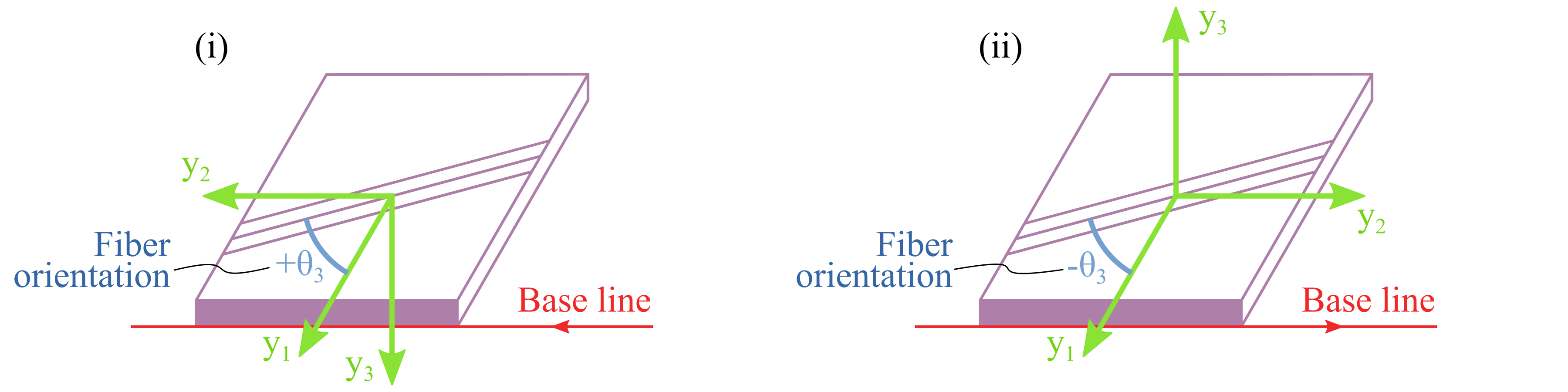
Figure 39 Relations among the base line direction, elemental frame y and fiber orientation (Note $y_2$ is parallel to the base line direction).#
1<layups>
2  <layup name="layup1" method="explicit list">
3    <layer lamina="lamina1">...</layer>
4    ...
5  </layup>
6  <layup name="layup2" method="stack sequence">...</layup>
7  <layup name="layup3" method="ply percentage">...</layup>
8  ...
9</layups>
Specification
<layup> - Root element for the definition of each layup.
name - Name of the layup.
method - Method of defining the layup. Choose one from ‘layer list’ (or ‘ll’) and ‘stack sequence’ (or ‘ss’). Default is ‘layer list’.
Explicit list#
This method requires user to write down the lamina name, fiber orientation and number of successive laminas with the same fiber orientation, layer by layer. Alternatively, a layer can also be defined by the name of a sublayup. A sublayup must appear before the layup where it is referenced. A template for one layer is shown below.
 1<layups>
 2  ...
 3  <layup name="...">
 4    <layer lamina="lamina_name"> angle:stack </layer>
 5    <layer lamina="lamina_name"> angle:stack </layer>
 6    <layer lamina="lamina_name"> angle:stack </layer>
 7    <layer layup="sublayup_name"/>
 8    ...
 9  </layup>
10  ...
11</layups>
Specification
<layer> - Material orientation and number of plies separated by a colon ‘angle:stack’. Default values are 0 for ‘angle’ and 1 for ‘stack’. If there is only one number presented in this element, then it is read in as ‘angle’, not ‘stack’, which is 1 by default.
lamina - Optional. Name of the lamina used in the current layer.
layup - Optional. Name of the sublayup used in the current layer. One and only one of lamina and layup should be used. ‘angle’ and ‘stack’ are not needed when layup is used.
An example for the layup shown in Fig. 38 is given in Listing 49 and Listing 50.
Stacking sequence code#
This method requires users to provide one lamina name and the stacking sequence code. A template is shown below.
1<layups>
2  ...
3  <layup name="..." method="stack sequence">
4    <lamina>...</lamina>
5    <code>...</code>
6  </layup>
7  ...
8</layups>
Specification
<lamina> - Name of the lamina used.
<code> - Stacking sequency code. Explained below.
Rules of writing the stacking sequence code
All fiber orientations should be put between a pair of square brackets
[];Different fiber orientations are separated by slash
/;After the right bracket, user can add
nsto indicate symmetry of the layup, wherenis the number of the symmetry operations needed to generate the complete layup;Successive laminae with the same fiber orientation can be expressed using colon like
angle:stack, whereangleis the fiber orientation andstackis the number of plies;If a group of fiber orientations is repeated, user needs to close them in a pair of round brackets
().
Examples
Code |
Complete sequence |
|---|---|
|
0, 90, 90, 0, 0, 90, 90, 0 |
|
45, -45, 45, -45, 0, 0, 0, 0, -45, 45, -45, 45 |
 1<materials>
 2  <material name="square" type="orthotropic">
 3    <density>...</density>
 4    <elastic>...</elastic>
 5  </material>
 6
 7  <material name="hexagon" type="orthotropic">
 8    <density>...</density>
 9    <elastic>...</elastic>
10  </material>
11
12  <lamina name="la_square_15">
13    <material> square </material>
14    <thickness> 1.5 </thickness>
15  </lamina>
16
17  <lamina name="la_hexagon_10">
18    <material> hexagon </material>
19    <thickness> 1.0 </thickness>
20  </lamina>
21</materials>
 1<layups>
 2  <layup name="layup_el" method="explicit list">
 3    <layer lamina="la_hexagon_10"> 45:2 </layer>
 4    <layer lamina="la_hexagon_10"> 90 </layer>
 5    <layer lamina="la_square_15"></layer>
 6    <layer lamina="la_hexagon_10"> -45:2 </layer>
 7    <layer lamina="la_square_15"> 0:2 </layer>
 8    <layer lamina="la_hexagon_10"> -45:2 </layer>
 9    <layer lamina="la_square_15"></layer>
10    <layer lamina="la_hexagon_10"> 90 </layer>
11    <layer lamina="la_hexagon_10"> 45:2 </layer>
12  </layup>
13
14  <layup name="layup_ss" method="stack sequence">
15    <lamina> la_square_15 </lamina>
16    <code> [(45/-45):2/0:4/90]2s </code>
17  </layup>
18</layups>