Laminate-type component#
For a cross section in PreVABS, laminates are created as segments. A segment is a unique combination of a base line and a layup. Segments are connected through different ways as shown here.
According to this, segments can be grouped into components. The rule of thumb is: if two segments are connected in the first two ways (‘V1’ and ‘V2’), then they belong to one component; if they are connected as the third way (‘T’), then they should be put into different components, and component 2 will be created after the finish of component 1.
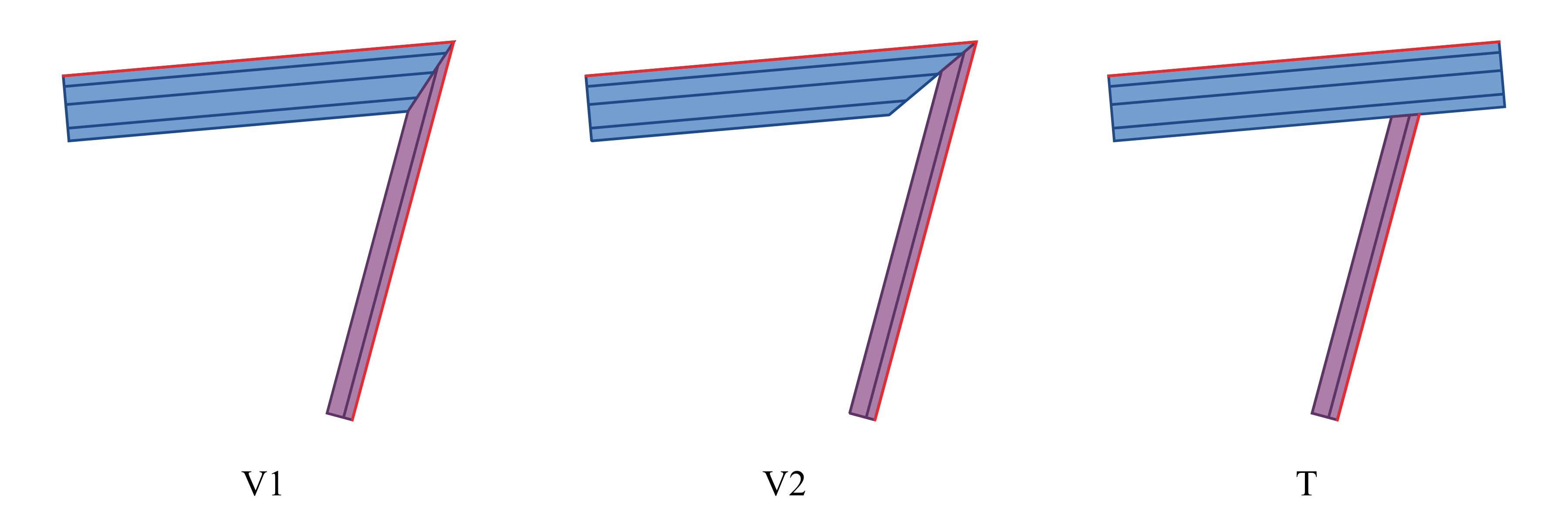
Figure 1 Three types of connections that can be created in PreVABS.#
A schematic plot of a segment is shown here. The base line provides a reference for the position and direction of the layup. Layers can be laid to the left or right of the base line. The direction is defined as one’s left or right, assuming one is walking along the direction of the base line.
By default the base line is the inner face of the layup (the first layer sits on
the base line). The optional position attribute on <baseline> moves the base
line to any through-thickness location of the layup: begin (default, inner
face), middle (mid-plane — half of the layup on each side of the base line),
end (outer face), or any fraction in [0, 1]. Whatever the position, the total
thickness and the layer sequence (from the base line outward) are unchanged; only
where the base line sits within the stack changes.
Setting direction="both" lays the layup up on both sides of the base line:
the base line becomes the mid-plane, the user’s layup reads from the base line
outward on each side, and the total thickness is doubled. It is realized as a
single segment equivalent to position="middle" with the layup mirrored about
the base line (so position is ignored when direction="both").

Figure 2 A typical segment in PreVABS and the relation between base line direction and layup direction.#
All segments definitions are stored in the main input file. The complete input will be discussed later since the overall configurations are also included in this file, which will be explained here.
Each component can have multiple segments.
There are two ways to define segments.
DEFINITION 1: Define segments individually#
Use a base line and a single layup to create the segment.
In this way, the layup covers the entire of the base line.
Each <segment> element has one attribute, name, and two child elements, <baseline> and <layup>.
The <layup> element has another attribute direction (see A typical segment in PreVABS and the relation between base line direction
and layup direction.).
Joint of two connecting segments can be changed from ‘V2’ (default) to ‘V1’ by using a <joint> element.
It requires the names of two segments, delimited by a comma (‘,’) and an attribute style specifying the joint type.
Example inputs for Three types of connections that can be created in PreVABS.:
<component name="cmp_surface">
  <segment name="sgm_1">
    <baseline> baseline1 </baseline>
    <layup direction="right"> layup1 </layup>
  </segment>
  <segment name="sgm_2">
    <baseline>...</baseline>
    <layup>...</layup>
  </segment>
  ...
  <joint style="2"> sgm_1,sgm_2 </joint>
  ...
</component>


<component name="cmp_web">
  <segment>
    <baseline> baseline2 </baseline>
    <layup direction="left"> layup2 </layup>
  </segment>
  ...
</component>
DEFINITION 2: Define segments collectively#
Use a base line and multiple layups to create multiple segments. Each layup can be assigned to a portion of the base line, using a beginning and an ending locations. These locations are normalized parametric positions on the base line. The beginning location must be smaller than the ending one. If the line is open, the location can only be a number between 0 and 1. If the line is closed, the location can be any number, even negative, as long as the length is not greater than 1. Then PreVABS will split the base line, combine layups and create segments automatically.
<component name="...">
  <segments>
    <baseline> l </baseline>
    <layup> layup1 </layup>
    <layup begin="0.2" end="0.75"> layup2 </layup>
    <layup begin="-0.1" end="0.5"> layup3 </layup>
    <layup begin="-0.6" end="-0.2"> layup4 </layup>
  </segments>
</component>
Example:
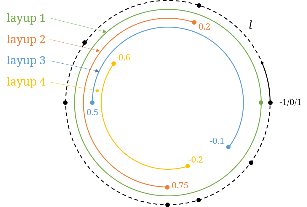
Figure 3 Segment layup range definition.#
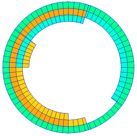
Figure 4 Segments plot.#
<component name="...">
  <segments>
    <baseline> base_line_3_name </baseline>
    <layup_side> left </layup_side>
    <layup> layup_1_name </layup>
    <layup begin="0.1"> layup_2_name </layup>
    <layup end="0.7"> layup_3_name </layup>
    <layup begin="0.2" end="0.9"> layup_4_name </layup>
    ...
  </segments>
</component>
Specification
DEFINITION 1
<segment>Root element of the definition of the segment.
nameName of the segment.
<baseline>Name of the base line defining this segment.
positionThrough-thickness location of the base line within the layup. Choose one from ‘begin’ (default), ‘middle’/‘center’, ‘end’, or any number in
[0, 1]. Ignored whendirection="both".
<layup>Name of the layup defining this segment.
directionDirection of layup. Choose one from ‘left’, ‘right’ and ‘both’. Default is ‘left’. ‘both’ lays the layup on both sides of the base line (total thickness doubled; base line at the mid-plane).
<joint>Names of two segments delimited by a comma (‘,’) that will be joined.
styleStyle of the joint. Choose one from ‘1’ and ‘2’. Default is ‘1’.
DEFINITION 2
<segments>Root element of the definition.
<baseline>Name of the base line defining these segments.
positionThrough-thickness location of the base line within the layups. Choose one from ‘begin’ (default), ‘middle’/‘center’, ‘end’, or any number in
[0, 1]. Applied to every interval. Ignored when<layup_side>is ‘both’.
<layup_side>Direction of the following layups. Choose one from ‘left’, ‘right’ and ‘both’. Default is ‘left’.
<layup>Name of the layup.
beginNormalized parametric beginning location of the layup on the base line. Default is ‘0.0’.
endNormalized parametric ending location of the layup on the base line. Default is ‘1.0’.