Fill-type component#
Besides creating laminates, user can use one material to fill a region. A typical usage is a nose mass in an airfoil type cross section. A schematic plot is shown Example usage of a fill-type component as a nose mass in an airfoil cross section.
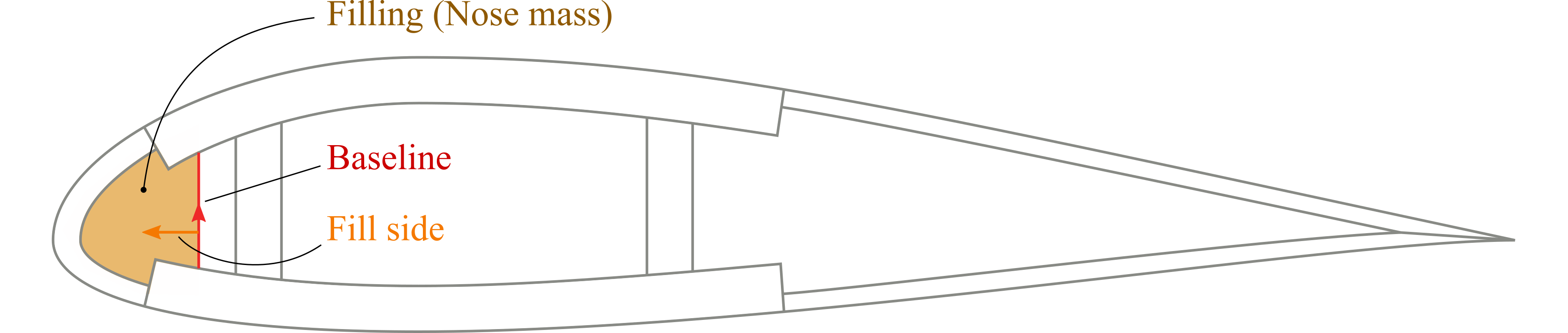
Figure 5 Example usage of a fill-type component as a nose mass in an airfoil cross section.#
The key to this type of component is the indication of the fill region. There are two things to pay attention to. First, make sure that the boundary of the region is well-defined. The region can be surrounded by a number of components. User can also create some extra base lines as new boundaries. Second, locate the region where the material will be filled into. Then can be done by using a point inside the region, or if there are extra base lines, user can indicate the fill side with respect to one of the lines, similar to defining layup side in a segment.
Fill-type components are also defined in the main input file.
A template is shown in Input syntax for the fill-type components..
A fill-type component is indicated by the attribute type="fill".
A <material> child element is required.
A <baseline> element is optional and is used to create extra boundaries.
This sub-element has one attribute fillside, which can be either left or right.
A <location> element is used to store the name of a point that is inside the desired fill region, and is also optional.
 1<component name="cmp_fill_1" type="fill">
 2  <location> point_fill </location>
 3  <material> material1 </material>
 4</component>
 5
 6
 7<component name="cmp_fill_2" type="fill">
 8  <baseline> bsl </baseline>
 9  <location> point_fill </location>
10  <material> material1 </material>
11  <mesh_size at="p1,p2"> 0.1 </mesh_size>
12</component>
13
14
15<component name="cmp_fill_3" type="fill">
16  <baseline fillside="right"> bsl_3 </baseline>
17  <material> material1 </material>
18</component>
Local mesh size#
Besides the mesh size set globally in the main input file, filling type components can be assigned local mesh sizes. This is usually for the purpose of reducing the total number of elements and computational cost. This feature is based on the embedded objects (points and lines) provided by Gmsh. Hence, one or more points need to be specified as the ‘seed’ of local mesh sizes.
<mesh_size at="p1,p2">0.1</mesh_size>
The mesh size will vary gradually from the local to the global setting. Hence, if only one point is used, then the local mesh size will only affect a circular region. If multiple points are used, then lines will be created by connecting points seqentially and assigned the local mesh size as well.
An example is provided below:
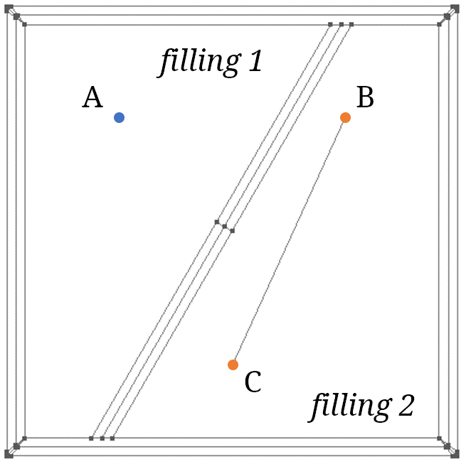
Figure 6 Local mesh definition.#
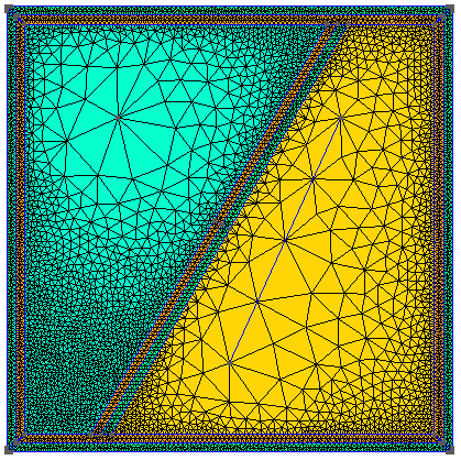
Figure 7 Local mesh plot.#
 1<component name="filling 1" type="fill" depend="...">
 2  <location> A </location>
 3  <material> material1 </material>
 4  <mesh_size at="A"> 0.2 </mesh_size>
 5</component>
 6
 7<component name="filling 2" type="fill" depend="...">
 8  <location> B </location>
 9  <material> material2 </material>
10  <mesh_size at="B,C"> 0.2 </mesh_size>
11</component>
Specification
<material>Name of the material to be filled. Required.
<location>Name of the point located in the fill region. Optional.
<baseline>Name of the base line defining part or complete boundary. Optional.
fillsideSide of the fill with respect to the base line. Optional.
<theta1>Rotating angle in degree about the x₁ axis. Optional. Default is 0 degree.
<theta3>Rotating angle in degree about the y₃ axis. Optional. Default is 0 degree.
<mesh_size>Local mesh size. Optional.
atA list of names of points where the local mesh size will be assgined. Required.