2.3. Create layers in 2D SG#
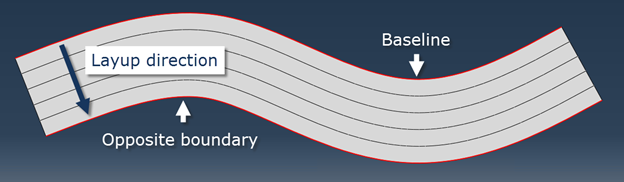
Figure 2.3.1 A layered structure.#
As shown in the figure, once the direction of layup is decided, the baseline is defined as the starting edge of the layup and the opposite boundary is the ending edge.
Before using the functions, user needs to provide the geometry of the cross-section, materials and composite sections.
2.3.1. Cut layers in a region#
Click the Create 2D SG: Assign layups button  to open the dialog box.
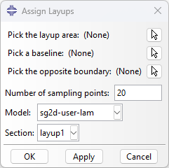
Figure 2.3.1.1 Create 2D SG: Assign layups dialog box.#
A layup area is the whole segment face before being partitioned into individual layers and the baseline is shown as in the figure above. These two objects are required for all type of laminates. The next two inputs, the opposite boundary and number of sampling points, are required only when the baseline and opposite boundary are not straight lines. The sampling points are used to replicate those curved edges in Abaqus sketch module. The more sampling points, the more accurate the geometry will be. But large number of points will greatly reduce the speed of building the part. The last two dropdown lists are for users to choose composite layups.
2.3.2. Remove layers in a region#
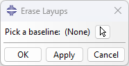
Figure 2.3.2.1 Create 2D SG: Erase layups dialog box.#
If a layup is assigned mistakenly, user can use this function to delete the wrong assignment. The baseline is the same as the one when assigning the layup. This function will help user to delete section assignments, sets and erase lines in the partition sketch, so that user can re-assign the area without worrying about duplicate or conflicting sets or section assignments.