Geometry and shapes#
The overall geometry and shape of a cross-section is defined by a series of base lines, forming the skeleton of it. The basic geometric elements are points and lines. The overall arrangement of the data is:
<baselines>
  <point name="p1">...</point>
  <point name="p2">...</point>
  ...
  <line name="name1" type="straight">...</line>
  <line name="name2" type="arc">...</line>
  <line name="name3" type="circle">...</line>
  <line name="name4" type="airfoil">...</line>
  ...
</baselines>
The root element is <baselines>.
It can contain arbitrary number of <point> and <line> elements.
[!NOTE] The element name
<baseline>is still accepted as an alias of<line>for backward compatibility, but<line>is preferred in new inputs.
Base points#
Base points are used to draw base lines, which form the skeleton of a cross section. They can be either actually on the base lines, or not, as reference points, for example the center of a circle. Points that are directly referred to in the definitions of base lines are called key points, such as starting and ending points of a line or an arc, or the center of a circle. The rest are normal points. The coordinates provided in the input file are defined in the basic frame z and then transformed into the cross-sectional frame x, through processes like translating, scaling and rotating. If none of those operations are needed, then those data also define the position of each point in the frame x.
Users can define points using the sub-element <point> one-by-one inside <baselines>, or list all points in a separate file and include it.
Points defined in the main XML file#
Using the XML format, points can be defined in the following ways:
Specify the complete coordinates with two numbers separated by spaces.
Confine the point on a line and specify the horizontal coordinate (\(z_2\) or \(x_2\)):
<point name="M" on="L" by="x2">3</point>When the host line is an
airfoilline that has both an upper and a lower surface at the requested \(x_2\) location, use thewhichattribute to pick which surface to land on:<point name="M_top" on="L" by="x2" which="top">0.3</point><point name="M_bottom" on="L" by="x2" which="bottom">0.3</point>Constrain a point as the midpoint of two existing points:
<point name="M" constraint="middle">p1 p2</point>

Specification
<point>: Coordinates of the point. For the first method, two numbers are needed and separated by blanks. For the second method, only one number is needed.Attributes
name: Name of the point. Required.on: Name of the line confining the point. Optional.by: Axis along which the coordinate is specified. Required if the point is defined on a line. Currentlyx2(aliasy) is the only implemented axis.which: Whenonreferences an airfoil-type line, choosetoporbottomto disambiguate the upper / lower surface. Default istop.constraint:middleto place the point at the midpoint of two named reference points listed as the element value. Default isnone.
Points defined in a data file#
The file storing these data is a plain text file, with a file extension .dat.
This block of data has three columns for the name and coordinate in the cross-sectional plane.
label_1  z2  z3
label_2  z2  z3
label_3  z2  z3
...
To include the point data file from inside <baselines>:
<baselines>
  <basepoints>
    <include>point_list_file_name</include>
  </basepoints>
  ...
</baselines>
The optional scale attribute on <include> multiplies all coordinates by a constant when the file is read:
<include scale="0.5">point_list_file_name</include>
[!NOTE]
<basepoints>is retained for backward compatibility but is deprecated. Prefer placing<point>elements directly inside<baselines>, or use the built-in<line type="airfoil">to consume a standard airfoil data file (see below).
Specification
Three columns are separated by spaces.
labelcan be the combination of any letters, numbers and underscores “_”.
[!NOTE] Normal points’ names can be less meaningful, even identical.
[!NOTE] If a base line is defined using the range method (explained below), e.g. ‘a:b’, then all points from ‘a’ to ‘b’ will be used. In this case, the order of points is important. Otherwise, points can be arranged arbitrarily.
Base lines#
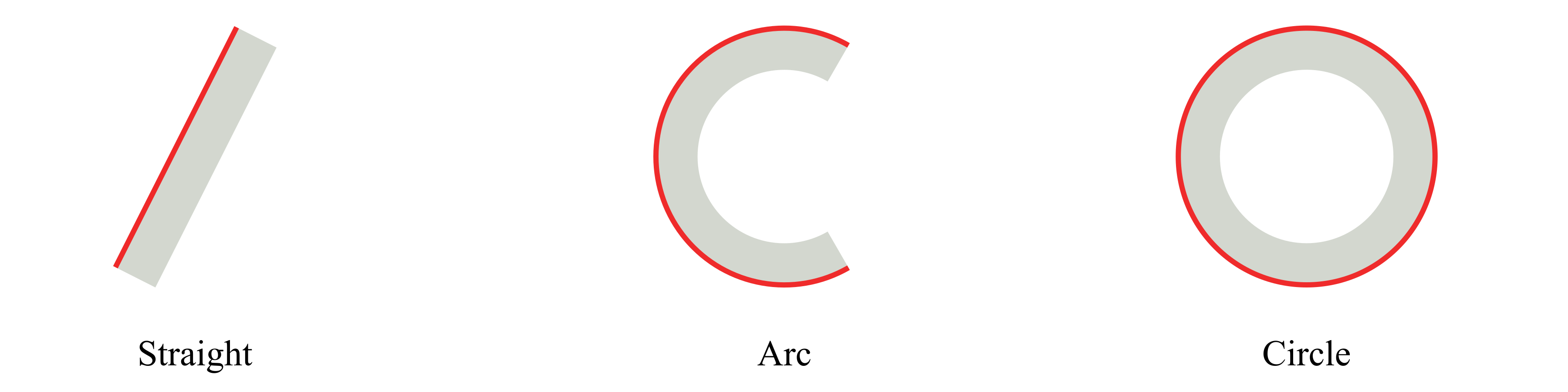
PreVABS can handle four types of base lines: straight, arc, circle and airfoil:
Some types have several ways to define the base line.
In PreVABS, all curved base lines are in the end converted into a polyline.
User can define polylines directly for spline, arc and circle.
Or, for arc or circle, user can use simple rules to draw the shape first and then PreVABS will discretize it.
The airfoil type reads a standard airfoil coordinate file (Selig or Lednicer format) and creates a closed polyline starting and ending at the trailing edge.
Each <line> element is a definition of a base line.
Each one has a unique name and an optional type, which can be straight (default), arc, circle, or airfoil.
Inside the line element, the straight and arc types have several different ways of definition, and thus the arrangements of data are different, which will be explained in details below.
Specification
<line>(or<baseline>): Definition of a base line (explained below).Attributes
name: Name of the base line. Required.type: Type of the base line. Optional. Choose one fromstraight(default),arc,circle,airfoil.method:direct(default) orjoin. Withmethod="join", the element value lists names of existing lines (one per child element) to be concatenated into a new line.
Straight#
For this type, the basic idea is to provide key points for a chain of straight lines.
The direction of a base line is defined by the order of the point list.
There are three ways defining a base line of this type:
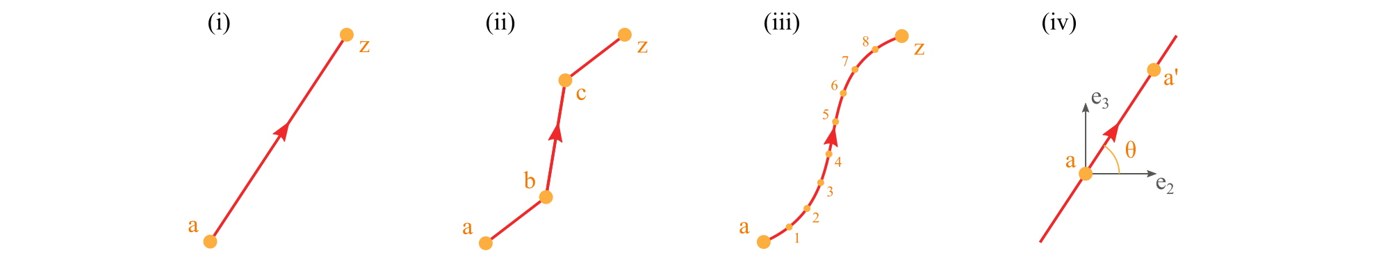
Use a comma-separated list of two or more points to define a polyline (i, ii).
<baselines>
    ...
    <line name="i" type="straight">
      <points> a,z </points>  <!-- Line defined by points a and z -->
    </line>

    <line name="ii" type="straight">
      <points> a,b,c,z </points>  <!-- Line defined by points a, b, c, and z -->
    </line>

    <line name="closed" type="straight">
      <points> a,b,c,z,a </points>  <!-- Closed polyline defined by points a, b, c, z, and a -->
    </line>
    ...
</baselines>
Use two points separated by a colon to represent a range of points (iii). The first two methods can be used in combination.
<baselines>
    ...
    <line name="iii" type="straight">
      <points> a:z </points>  <!-- Line defined by points from a to z -->
    </line>

    <line name="iii-2" type="straight">
      <points> a:z,b,c </points>  <!-- Line defined by points from a to z and b and c -->
    </line>
    ...
</baselines>
Use a point and an incline angle to define a straight line (iv). In this case, PreVABS will calculate the second key point (a’) and generate the base line. The PreVABS-computed second key point will always be “not lower” than the user-provided key point, which means the base line will always be pointing to the upper left or upper right, or to the right if it is horizontal.
<baselines>
    ...
    <line name="iv" type="straight">
      <point> a </point>  <!-- Line defined by the point a and an angle theta -->
      <angle> theta </angle>
    </line>
    ...
</baselines>
[!NOTE] Use
type="straight"for splines.
Specification
<points>: Names of points defining the base line, separated by commas (explicit list), or colons (range). Blanks are not allowed between points names.<point>: Name of a point.<angle>: Incline angle of the line. The positive angle (degree) is defined from the positive z₂ axis, counter-clockwise.
The <point>+<angle> form accepts an optional loc attribute on the <point> to control whether the user-provided point is the line’s midpoint (loc="inner", default) or its starting endpoint (loc="end").
Arc#
A real arc can also be created using a group of base points, in which case the straight type should be used.
The arc type provides a parametric way to build this type of base line, then PreVABS will
discretize it.
There are several ways of defining an arc.

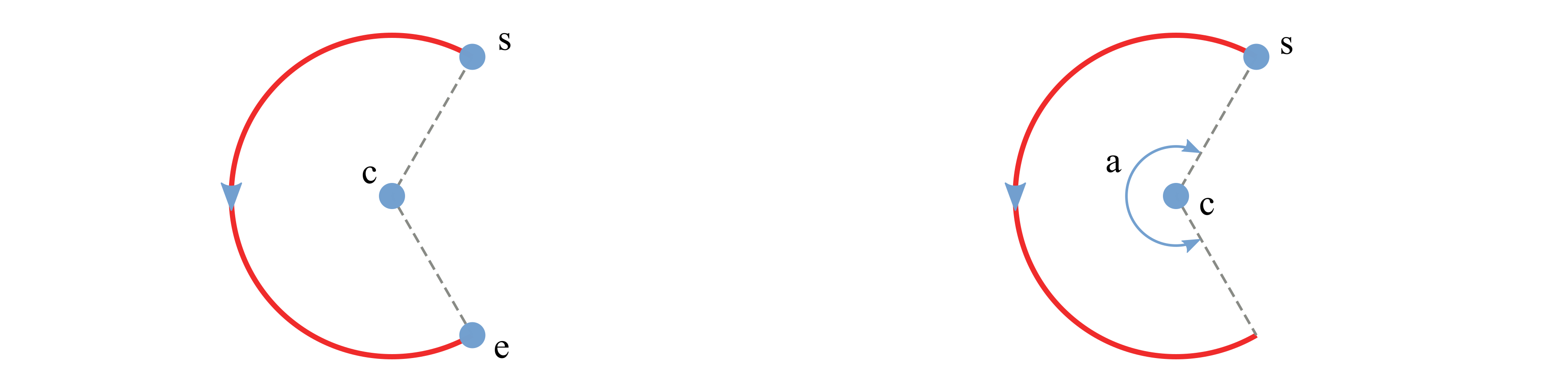
Use center, starting point, ending point and direction.
Use center, starting point, ending point and angle.
Use center, starting point, angle and direction.
Use starting point, ending point, and either
<radius>or<curvature>, with an optional<side>to choose which side of the chord the arc bends toward. A zero curvature degenerates to a straight chord.
Example inputs:
<baselines>
    ...
    <line name="left" type="arc">
        <center> c </center>
        <start> s </start>
        <end> e </end>
        <direction> ccw </direction>
        <discrete by="angle"> 9 </discrete>
    </line>

    <line name="right" type="arc">
        <center> c </center>
        <start> s </start>
        <angle> a </angle>
        <discrete by="number"> 10 </discrete>
    </line>

    <line name="by_radius" type="arc">
        <start> s </start>
        <end> e </end>
        <radius> r </radius>
        <side> right </side>
        <direction> ccw </direction>
    </line>
    ...
</baselines>
Specification
<center>: Name of the center point.<start>: Name of the starting point.<end>: Name of the ending point.<direction>: Direction of the circular arc. Choose from ‘cw’ (clockwise) and ‘ccw’ (counter-clockwise). Default is ‘ccw’.<angle>: Central angle of the arc.<radius>/<curvature>: Used together with<start>and<end>to size the arc; provide one or the other.<side>:leftorrightof the chord (start→end). Default isright.<discrete>: Number of discretization. Ifby="angle", then new points are created every specified degrees of angle. Ifby="number", then specified number of new points are created and evenly distributed on the arc.Attributes
by: Choose one fromangleandnumber. Default isangle.
Circle#
Defining a circle is simpler than an arc.
User only need to provide a center with radius or another point on the circle.
The corresponding element tags are <center>, <radius> and <point>.
There are two ways of defining a circle:
Use center and radius.
Use center and a point on the circle.
A sample input file demonstrating the two methods:
<baselines>
    ...
    <line name="circle1" type="circle">
        <center> c </center>
        <radius> r </radius>
    </line>

    <line name="circle2" type="circle">
        <center> c </center>
        <point> p </point>
        <direction> cw </direction>
    </line>
    ...
</baselines>
Specification
<center>: Name of the center point.<radius>: Radius of the circle.<point>: Name of a point on the circle.<direction>: Direction of the circle. Choose fromcw(clockwise) andccw(counter-clockwise). Default isccw.<discrete>: Number of discretization (same semantics as for arcs).
Airfoil#
type="airfoil" consumes a standard airfoil coordinate file and produces a closed polyline that starts and ends at the trailing edge \((1, 0)\) and passes through the leading edge \((0, 0)\).
Both Selig (single block) and Lednicer (upper / blank line / lower) formats are supported.
<baselines>
    <line name="ln_af" type="airfoil">
        <points data="file" format="1" header="1">mh104.dat</points>
        <flip>1</flip>
        <reverse>1</reverse>
    </line>
</baselines>
Specification
<points>: Path to the airfoil data file (relative to the main XML file).Attributes
data: Source of the data. Currently onlyfileis supported.format: Airfoil file format.1/selig/s*for Selig,2/lednicer/l*for Lednicer. Default is2.header: Number of header rows in the data file to skip. Default is0.direction:1/ccw/forwardor-1/cw/reverse. Default is1.
<flip>: Optional. Mirror the airfoil after construction. The element value is a boolean (1/0/true/false); attributesaxis(2/x2/yor3/x3/z, default2) andloc(mirror location, default0.5) control the reflection.<reverse>: Optional. If true, reverse the order of vertices on the line after all other transforms.
Two canonical leading-edge and trailing-edge vertices are always created and named <linename>_le and <linename>_te.
Interior vertices are named <linename>_p1, <linename>_p2, ….