Coordinate systems#
There are three coordinate frames used in PreVABS:
z is a basic frame, for the normalized airfoil data points for instance;
x is the final frame;
y is the local frame for each element.
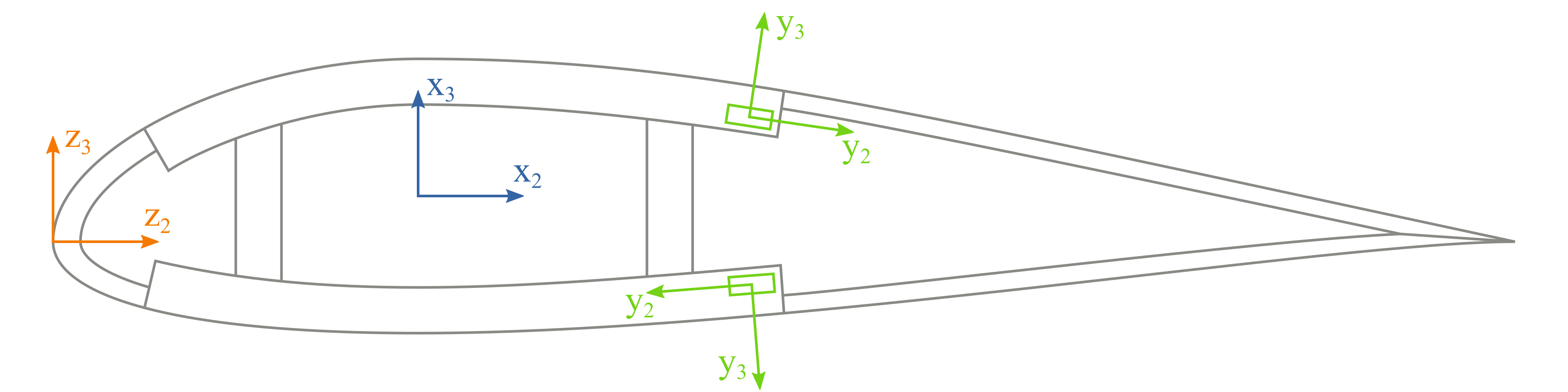
Here, \(x_1\), \(y_1\), and \(z_1\), are parallel to the tangent of the beam reference line and pointing out of the paper.
The basic frame is where base points are defined.
The cross-sectional and elementary frames have the same definitions as those in VABS.
User can define the topology of a cross section in the basic frame z and use manipulations like translation, scaling and rotation to generate the actual geometry in x.
For an airfoil cross section, airfoil surface data points downloaded from a database having chord length 1 are in the frame z, and they are transformed into the frame x through translation (re-define the origin), scaling (multiplied by the actual chord length), and rotation (attack angle) if necessary:
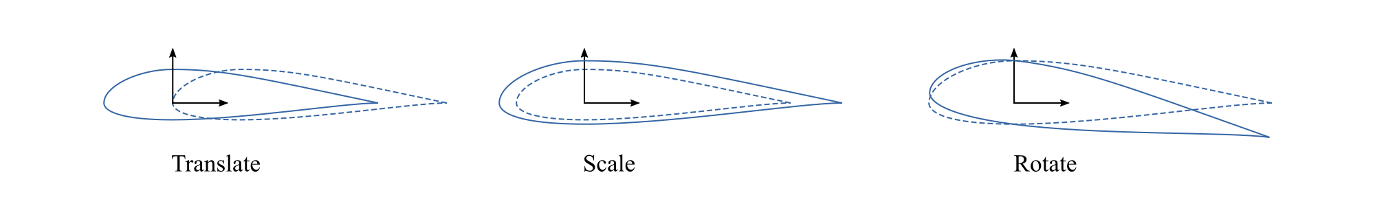
More details about this transformation can be found in this section.
In PreVABS, the definition of the elementary frame y follows the rule that the positive direction of \(y_2\) axis is always the same as the direction of the base line, and then \(y_3\) is generated based on \(y_1\) and \(y_2\) according to the right-hand rule. More details about the base line can be found in this section.